Seismic Data Acquistion
BCE offers highly configurable seismic data acquisition systems (SDASs). These systems are based upon a Plug and Play (PnP) philosophy where systems with a large number of channels are easily assembled from uniaxial and triaxial signal conditioning boards (SCBs). For example, a six channel system is configured by plugging two triaxial SCBs together. This allows for the quick decomposition or assembly of SDASs depending upon the needs of the investigator. The signal conditioning boards are also designed to simultaneously acquire data from passive geophone and/or high precision active pcb accelerometer sensors depending on the job requirements.
BCE's Signal Conditioning boards highlights:
- Differential pre-amplifier stage.
- Programmable gain amplifier.
- Programmable low pass filter.
- Trigger unit with programmable gain.
General specifications of the Signal Conditioning unit:
- Power Supply - Requirements: 6 - 18V/400mA AC or DC
Differential pre-amplifier specifications:
- Noise: <10ηV/√Hz
- Gain: 3.5dB
- Common Mode Suppression: >90dB
System Gain specifications (full scale signal +/- 10V) :
- Gains: 0dB - 84dB adjustable in 6dB increments (14 positions).
Frequency range: 1Hz - 10kHz +/- 3dB
Programmable Filter:
- User selectable 2nd and 4th order low pass filter anti-aliasing filters.
- Dynamically adjustable anti-aliasing filter based on 1/3 sampling frequency.
Trigger:
- Adjustable trigger level.
Other signal conditioning features:
- Independent 2mA/18V current sources for excitation of sensors available via jumper selections for both Trigger and Linear Amplifier.
- Programmable settings via software based selections.
BCE offers customized data acquisition software. The data acquisition software can be based upon existing BCE software packages such as SC1-DAC™ (uniaxial), SC2-DAC™ (biaxial), SC3-DAC™ (triaxial), SC6-DAC™ (true interval six channel seismic cone system) and μSeis-DAC™ (passive-μ seismic) or client specified requirements and user interface.
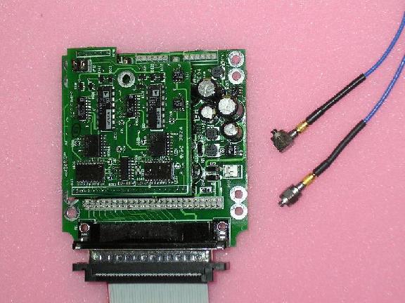
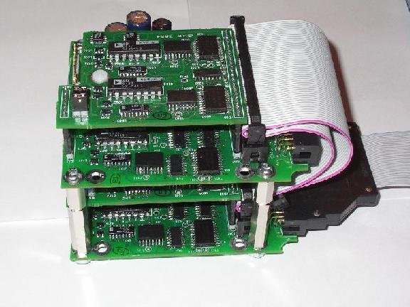
Figure 1. (a) Uniaxial + Dedicated Trigger Channel Configuration
Figure 1. (b) Six Channel + Dedicated Trigger Channel Configuration